2 Jun 2026
- 0 Comments
You point your virtual telescope at Orion’s Belt. The stars look right. But when you switch to a high-power eyepiece, the moon looks like a dinner plate instead of a coin. Something is off. It’s not the graphics engine. It’s the math behind the lens.
Calibrating Apparent Field of View against True Field of View is the difference between a pretty picture and a useful tool. In astronomy simulations, this calibration determines whether your virtual observing session matches reality. If the numbers don’t line up, your star hopping skills won’t transfer to the real sky. Your exit pupil calculations will be wrong. And that deep-sky object you’re trying to find? It’ll vanish off the edge of your simulated view before you even know it’s there.
This isn’t just about tweaking sliders. It’s about understanding how light bends through glass and how software renders that bend on a flat screen. Let’s fix the mismatch.
The Core Problem: Why Simulators Lie About Space
Most astronomy simulators treat the sky as a simple dome projected onto your monitor. They calculate True Field of View (TFOV) based on sensor size or eyepiece focal length, but they often ignore the curvature of human vision. This creates a distortion called "barrel effect" where straight lines bow outward near the edges.
When you look through a real telescope, your eye sits at a specific distance from the eyepiece. The Apparent Field of View (AFOV) is the angular width of the image as seen by your eye inside the eyepiece. A standard Kellner eyepiece might have an AFOV of 50 degrees. A premium wide-field Plössl can hit 68 degrees. An ultra-wide Nagler pushes past 82 degrees. These aren’t marketing gimmicks; they change how much of the sky you see without moving your head.
In a simulator, if the software assumes a fixed 50-degree AFOV for all eyepieces, your wide-field views will feel cramped. Your narrow-field views will feel stretched. The calibration gap grows wider the more extreme the optics get.
Step-by-Step Calibration Process
To calibrate correctly, you need to bridge the gap between optical physics and digital rendering. Follow these steps to align your simulator with reality.
- Identify Your Eyepiece Profile. Not all eyepieces are created equal. Gather the manufacturer specs for your virtual gear. Look for the exact AFOV value. For example, a Celestron X-Cel LX 25mm has a 68° AFOV. A generic 32mm Plossl usually sits around 50°. Input these values into your simulator’s eyepiece database. Don’t guess. Use the spec sheet.
- Set the Telescope Focal Length. TFOV depends heavily on the telescope’s focal length. If you’re simulating an 8-inch Dobsonian with a 1200mm focal length, ensure that number is locked in. Changing the focal ratio (f/6 vs f/10) changes the magnification, which directly alters the TFOV.
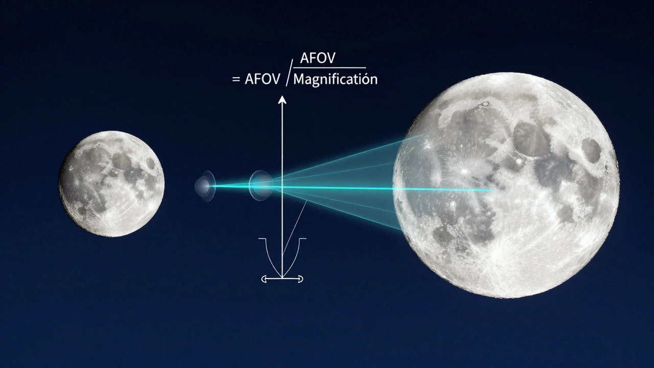
- Calculate the Baseline TFOV. Use the standard formula:
TFOV = AFOV / Magnification
Where Magnification = Telescope Focal Length / Eyepiece Focal Length.
For our 1200mm scope and 25mm eyepiece: Mag = 48x. TFOV = 68 / 48 = 1.41 degrees. This is your target number. - Adjust the Simulator’s Projection Model. Most modern simulators allow you to choose between "Flat," "Spherical," or "Fisheye" projections. For accurate AFOV/TFOV matching, select "Spherical" or "Orthographic" depending on your viewing angle. Flat projections distort edge stars significantly at wide fields.
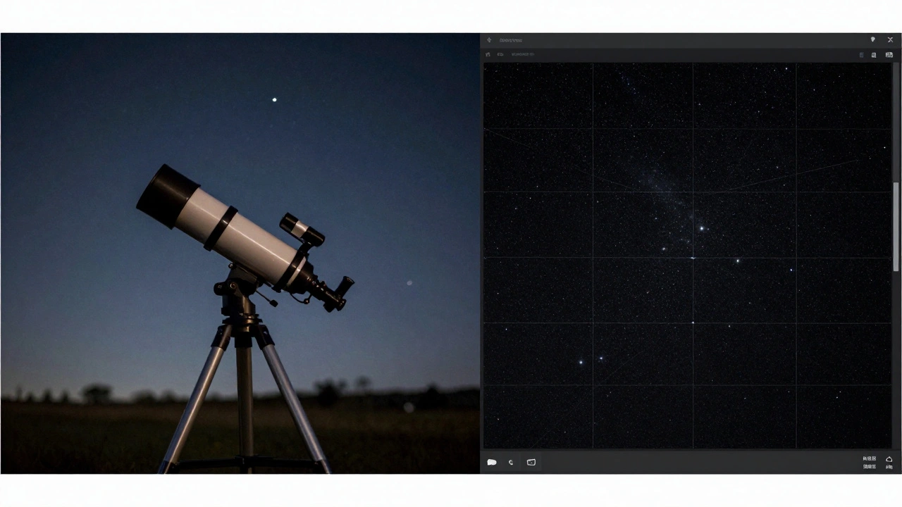
- Verify with a Known Object. Point your simulator at the Moon. The Moon’s diameter is approximately 0.5 degrees. At 1.41 degrees TFOV, the Moon should occupy roughly one-third of the horizontal width of your view. If it looks half that size, your AFOV input is too low. If it fills half the screen, your AFOV is too high. Adjust until the proportions match.
Understanding the Math Behind the Lens
Why does this matter? Because Magnification is not just a zoom slider. It’s a ratio that dictates how much of the sky gets compressed into your eye’s pupil. When you calibrate AFOV and TFOV, you’re essentially telling the software how to stretch or compress pixels to mimic that compression.
Consider the exit pupil. This is the beam of light exiting the eyepiece and entering your eye. It’s calculated as Eyepiece Focal Length / Telescope Focal Ratio. In our example: 25mm / 6 = 4.17mm. This fits comfortably within a dark-adapted human pupil (which opens to about 5-7mm). If your simulator doesn’t account for this, stars may appear too bright or too dim compared to reality. Proper TFOV calibration ensures the surface brightness of nebulae matches what you’d see visually.
| Eyepiece Type | Typical AFOV (Degrees) | Best Use Case | Distortion Level |
|---|---|---|---|
| Kellner | 40° - 50° | High power planetary viewing | Low |
| Plossl | 50° - 52° | General purpose observing | Low-Medium |
| Erfle | 60° - 70° | Wide-field deep sky | Medium |
| Nagler/Tourist | 82° - 100°+ | Immersive star clusters | High (Barrel) |
Common Pitfalls in Simulation Setup
Even after following the steps, things can go sideways. Here’s what trips up most users.
- Ignoring Eye Relief. Eye relief is the distance your eye must sit from the eyepiece to see the full field. Short eye relief (common in older designs) means you have to press your face close to the lens. Simulators often assume perfect positioning. If you’re wearing glasses, your effective AFOV shrinks because your eye isn’t at the optimal nodal point. Some advanced simulators let you adjust "eye position"-use it if you wear corrective lenses.
- Mixing Up Sensor Sizes for CCD Imaging. If you’re simulating astrophotography rather than visual observing, TFOV depends on camera sensor dimensions, not eyepiece AFOV. A full-frame DSLR has a different crop factor than a small APS-C sensor. Ensure your simulator knows whether you’re using a visual eyepiece or a digital sensor. The math shifts from
AFOV/MagtoSensor Width / Focal Length * 57.3. - Assuming Linear Scaling. Doubling the magnification doesn’t always halve the visible area perfectly due to vignetting. Real eyepieces darken at the edges. High-end simulators include vignetting profiles. Turn them on. Without them, your simulated field looks unnaturally bright at the borders, tricking your brain into thinking the TFOV is larger than it is.
Advanced Tweaks for Precision Users
If you’re using your simulator for serious planning-like predicting where a comet will pass relative to a star cluster-you need pixel-perfect accuracy. Here’s how to get there.
First, enable Chromatic Aberration Simulation. Refractor telescopes suffer from color fringing, especially at high powers. While this doesn’t change TFOV numerically, it affects perceived sharpness at the edges. If your simulator blurs the edges realistically, you’ll instinctively trust the center more, which mirrors real-world observing behavior.
Second, check the Star Density Algorithm. Wide-field views (low power) show thousands of stars. Narrow-field views (high power) show fewer. If your simulator keeps star density constant regardless of zoom, it breaks immersion. Look for settings labeled "Magnitude Limit" or "Sky Background Noise." Adjust these so that faint stars disappear as you increase magnification, just as they do in reality.
Finally, consider atmospheric seeing. Turbulence blurs fine detail. A calibrated TFOV is useless if the software renders Jupiter’s bands as razor-sharp lines every night. Set your seeing conditions to match your location. Portland, Oregon, typically sees 2-3 arcseconds of seeing under good conditions. Inputting this adds realistic blur, helping you judge whether your resolution limits are optical or atmospheric.
Testing Your Calibration
How do you know you’ve done it right? Go outside. Grab your real telescope. Find a double star with a known separation, like Mizar and Alcor (separated by 14.4 arcminutes). Switch to the same eyepiece and magnification in your simulator. Measure the pixel distance between the stars in both views. They should match within 5%. If they don’t, revisit your AFOV input. Small errors compound quickly at high magnifications.
Another test: Star Hopping. Plan a path from Polaris to Vega using only low-power fields. Execute the same path in the simulator. If you lose track of landmarks in the sim but not in reality, your TFOV is likely too wide. If you bump into objects unexpectedly, it’s too narrow. Adjust until the navigation feels identical.
What is the difference between AFOV and TFOV?
Apparent Field of View (AFOV) is the angle of the view as seen through the eyepiece itself, determined by the eyepiece design. True Field of View (TFOV) is the actual patch of sky you see, calculated by dividing AFOV by the magnification. AFOV is a property of the eyepiece; TFOV is a property of the entire optical system.
Why does my simulator show a wider view than my real telescope?
This usually happens when the simulator assumes a higher AFOV than your actual eyepiece provides. For example, if your eyepiece is 50° but the sim defaults to 68°, your TFOV will be artificially inflated. Check your eyepiece profile settings and input the correct manufacturer specification.
Do I need to recalibrate if I change telescopes?
Yes. Since TFOV depends on telescope focal length, changing scopes changes the magnification for any given eyepiece. You must update the telescope’s focal length in the simulator to maintain accurate TFOV calculations.
How does eye relief affect field of view calibration?
Poor eye relief positioning can cause vignetting, effectively reducing the usable AFOV. If you wear glasses or have trouble getting close to the eyepiece, your effective field may shrink by 5-10%. Advanced simulators allow you to adjust eye position to compensate for this loss.
Can I use the same calibration for astrophotography simulations?
No. Astrophotography uses sensor dimensions, not eyepiece AFOV. You must switch your simulator to "Camera Mode" and input your sensor’s physical width and height. The calculation changes from angular optics to linear geometry based on focal length and sensor size.